
bilibli
https://www.bilibili.com/video/BV1vGRnYoEjn
https://www.bilibili.com/video/BV1nZfHYSEMK/
https://www.bilibili.com/video/BV1CYREYvEag/
basic
Instructions:
- Multiple choice support: Only when the assembly batch mode is selected and three views are created, multiple choices are supported
- a key! Partial commands support multiple selection of cutting lists under parts
- File differentiation and avoidance: Avoidance
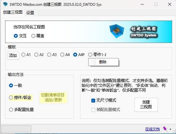
Steps to add a template
Steps:
- Change name: Choose a regular engineering drawing and modify it to the template name you need, such as A2-b company SLDDRW
- Delete all annotations, technical requirements, keep only the main view
- In creating three views, click “Add” and select A2-b company SLDDRW
- Repeat the first 3 steps and add A0~A4P
Precautions
- Verify the legality of the engineering drawing: Please close all open SW files and only open A2-b company SLDDRW, The content is defect free, and the frame can link all part attributes normally (can’t link? Please use SWTDO default template). Right clicking can open the corresponding part.
- Purely custom templates cannot guarantee the full functionality of SWTDO, such as property formatting and Prod system; But if the drawing is created and modified based on the SWTDO default template, it will be able to apply full functionality
Learn More About Template Settings
https://www.bilibili.com/video/BV1Kp4y1A7TC
Create three views and distinguish them from view annotations
1. Create three views, automatically dimension parts, draw sketch dimensions based on user logarithmic models, and passively annotate them;
2. Create three views for entity diagrams of multiple entities: first image, based on user model dimensions, passively annotated; Other, active annotation based on view annotation
3. For assembly, only output the external dimensions.
4. View annotation, based on active annotation, can annotate components without SW features, such as STEP save, reference, mirror, etc
5. Create three views with up to 50 automatic changes based on BOM settings, cutting list settings, multi entity types, sheet metal types, etc;
One sentence understanding: View annotation is only required when the dimensions of creating a three view are not working properly
Output Method Description
- Multi body batch output (applicable to any situation except for multiple configurations):
The output will generate a single file, multi drawing format engineering drawing (which will contain at least 2 drawings). The drawing name of the first drawing is the configuration name, and the other drawings are the project names of the cutting list. The cutting list drawing will be attached with cutting list attribute information. If unfolded, sheet metal entity is checked, an unfolded view will be added. All views will be resized and the spacing position will be automatically adjusted. - Ordinary
The drawing name is the configuration name, and the drawing file name is the same as the component name - Multi configuration batch output
The drawing name is the configuration name. How many configurations are there and how many drawings are generated? Note that it is a single file and multiple drawings; SWTDO only has digital to analog output and entity list, supports single file output of multiple files, limited to digital to analog. In any case, we follow the one-to-one principle, which is a mandatory rule for BOM indexing.
Two methods for automatic sizing
Multi entity, TDO’s engineering drawing output is single file, multi drawing, and we used 5 methods for annotation.
- Mixed annotation: Based on our production experience, we mix multiple annotation methods.
- Appearance annotation: (assembly, sheet metal recommendation) Only output the appearance, with defects in column and circular edges,
- Active annotation: (Step, mirror, etc., recommended for views without SW features) Based on API specific functions for visible lines in engineering drawing views, it has a position setting method
- Traverse visible: no explanation for now
- Passive annotation: (Recommended for views with SW features, except for sheet metal) In the digital model, what is your size? In the engineering drawing, it is completely replicated and supports annotation, welding parts, irregular holes, etc. The most complete annotation method supports engineering drawing size reverse drive digital model changes. Whether it is aesthetically pleasing or not depends on the dimension annotation method in the numerical model
combo
- Batch specification of fixed surfaces for creating three views and sheet metal
- Create attribute formatting for three views+entity list
- Create three views+drawing standards
- Create Three Views+Frame Replacement
- Create three views+view annotation
- Create three views+cutting list
Cutting list update/addition, this tool has extremely high value!!
This tool is based on the already created three views. When the part is a welded component and the user has manually selected the cutting list item (supports multiple selections)
On the basis of the existing three views, solid drawings will be added or replaced with strict renaming and change logic. The workload compressed based on this tool is enormous, especially for steel structures and large cutting lists
BOM template and cutting list table template
Path changes are not supported and must be stored in the SWTDODT default folder
But file names can be modified or added
Preset positions for BOM and Cutlist tables
When running batch processing, if there is a BOM or Cutlist table with a position that does not match the default template position, please learn how to preset positioning points in the template.
In human terms, for engineering drawing templates, edit the drawing format, find a point, right-click to set it as the BOM positioning point, SWTDO defaults to the BOM positioning point at the top right corner of the frame, Cutlist defaults to the positioning point at the top right corner of the title block
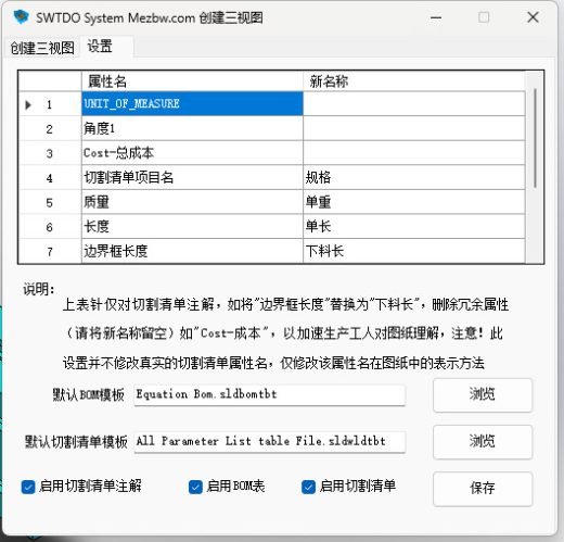
Settings - Cutting List Attribute Table Settings
This table is for the purpose of annotating the cutting list in solid drawings
Can replace textual expressions and delete unnecessary annotation items
This table does not modify the actual cutting list attribute names, only adjusts the presentation in the drawing.
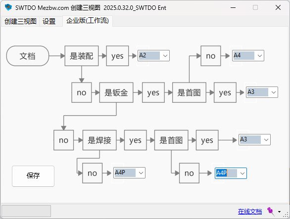
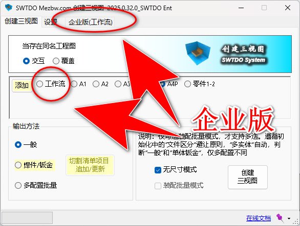
Enterprise specific workflow
Controlled by SWTDO Enterprise Edition’s workflow module C-end, all U-ends use drawing templates
Under the workflow, the drawing type will be automatically determined based on the preset, the drawing template will be adjusted, and the output results will be dynamically changed
contrast:
Personal version, only a unique image frame can be applied for each batch processing.
Workflow: Automatically adapt to preset drawing frames, modify according to attributes, and output images such as sales drawings and business drawings. Due to the significant differences in content between business drawings and production drawings, the display content is different


